


Stokta Var
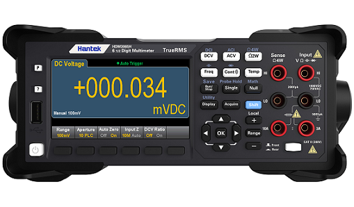
Hantek HDM3055 1 μV Yüksek Çözünürlüklü 5 1/2 Reading Multimetre
33.782,40 TL Kdv Dahil
17.884,80 TL Kdv Dahil
%47
KDV Dahil Fiyat
17.884,80 TL
9.121,25 TL den başlayan taksitlerle!
Kategori
Marka
Stok Kodu
557BX9ZK9L
Havale
17.348,26 TL
(%3,00 havale indirimi)
HDM3055 1 μV Yüksek Çözünürlüklü 5 1/2 Reading Multimetre Genel Özellikleri:
| Model | HDM3055 |
| Digit Sayısı | 5 1/2 |
| Max Okuma Oranı | 30, 000 readings/s |
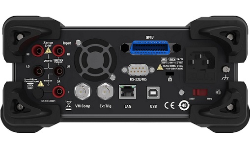
| I/O Arayüzü | USB, RS232/485 LAN, GPIB |
| Yıllık DC Voltaj Doğruluğu | 150 ppm |
- 1 μV yüksek çözünürlüklü 5 1/2 okuma multimetresi
- Geçici sinyallerin yakalanmasını kolaylaştıran 30 kS/s yüksek hızlı örnekleme frekansı
- Ön ve arkada iki set giriş arayüzü ile kabloları düzenlemede kolaylık sağlar
- Standart çubuk grafik, histogram, trend grafiği ve veri istatistikleri işlevleri
- Voltajı ve frekansı eş zamanlı olarak görüntüleyen çift ekran ölçüm fonksiyonu
- AC voltajının gerçek RMS'i ve AC akımının gerçek RMS ölçümleri
- 0,1 μV çözünürlük, basit kullanım, esnek parametre ayarı
- Çeşitli ölçüm fonksiyonları: DC voltaj, AC voltaj, DC akım, AC akım, 2 hat direnci, 4 hat direnci, kapasitans, diyot, bağlantı, frekans, periyot, sıcaklık, akım aralığı 10 A'ya ulaşır
- 4,3 inç renkli LCD ekran
- Güvenlik standardı: CAT II 300 V
- SCPI uzaktan kumanda komutunu destekler, piyasadaki yaygın multimetre komut setleriyle uyumludur ve üst düzey bilgisayar kontrol yazılımıyla standarttır.
- Yapılandırma arayüzleri: USB Aygıtı, USB Ana Bilgisayarı, LAN (HDM3055B), GPIB (HDM3055H).
| Model | HDM3055H | HDM3055B | HDM3055A | HDM3055S | HDM3055 |
| Çözünürlük bit | 5 1/2 | 5 1/2 | 5 1/2 | 5 1/2 | 5 1/2 |
| DCV basic precision | 150 ppm | 150 ppm | 150 ppm | 150 ppm | 150 ppm |
| Maximum okuma oranı | 30,000 rdgs/s | 30,000 rdgs/s | 30,000 rdgs/s | 30,000 rdgs/s | 30,000 rdgs/s |
| Hafıza | 10,000 readings | 10,000 readings | 10,000 readings | 10,000 readings | 10,000 readings |
| Çift Ekranlı Ölçüm Fonksiyonu | √ | √ | √ | √ | √ |
| Statistical graph | Histogram, bar graph, trend graph |
Histogram, bar graph, trend graph |
Histogram, bar graph, trend graph |
Histogram, bar graph, trend graph |
Histogram, bar graph, trend graph |
| Arayüz | USB、RS232/485、LAN、GPIB | USB、RS232/485、LAN | USB、RS232/485 | USB、RS232/485 | USB、RS232/485 |
| Giriş Terminali | Front-panel Rear-panel |
Front-panel Rear-panel |
Front-panel Rear-panel |
Rear-panel | Front-panel |
Bu ürüne ilk yorumu siz yapın!
